
RK Control Valve Positioners position the Control Valve accurately with respect to the input signal from the controller, regardless of packing box friction, actuator hysteresis or unbalanced forces on the valve plug. Thus, RK Control Valve Positioner ensures a reliable and accurate operation of the control valve.
RK Valve Positioner Model VP5 is simple '!°. construction, stable in operation, force balanced and provides fast and
accurate positioning. It is suitable for mounting ..›aphragm or piston actuators, double acting or single acting.
VP5 Positioner, is available with two different mounting options. 1) On the side of the actuator yoke. 2) Front mounted on
the yoke. For rotary action the unit is directly coupled to actuator rotary shaft. Positioner type rotary can be used for either
Linear or rotary operation. Standard cam is profiled for linear operation; however, special profile can be developed on the
cam for any desired specific characteristics.
Positioner action can be reversed without involving additional parts. Zero and stroke range both are adjustable. Linear
stroke is adjustable from / 2 " to 5” and rotary movement 60°/90’. The input signal can be either pneumatic or current signal
through I/P conversion module that may be mounted directly on the manifold. Split range operation can be conveniently
achieved without using additional parts.
OPERATION
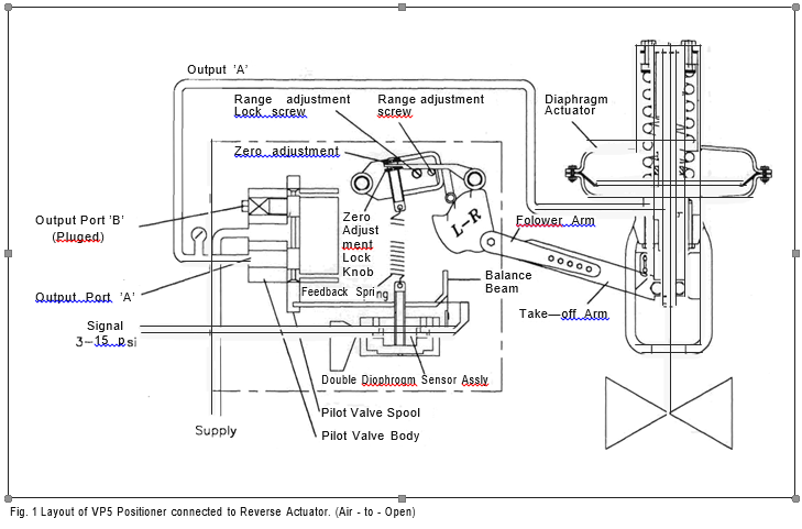
Fig. 1 shows the layout drawing of Direct acting positioner
connected to a reverse actuator. When positioner is
connected to single acting actuator, the output port ‘A’ of the
pilot valve is connected to the actuator whereas the output
port ‘B’ is plugged as shown.
-rhe instrument signal is admitted to the double diaphragm
sensor assembly. An increase in the control signal pressure
results in downward movement of the pilot valve spool,
thereby pressurizing output port ‘A’. This, in turn operates
the actuator moving the actuator stem upward until
balanced by the down- ward force exerted through the feed
back calibration spring.
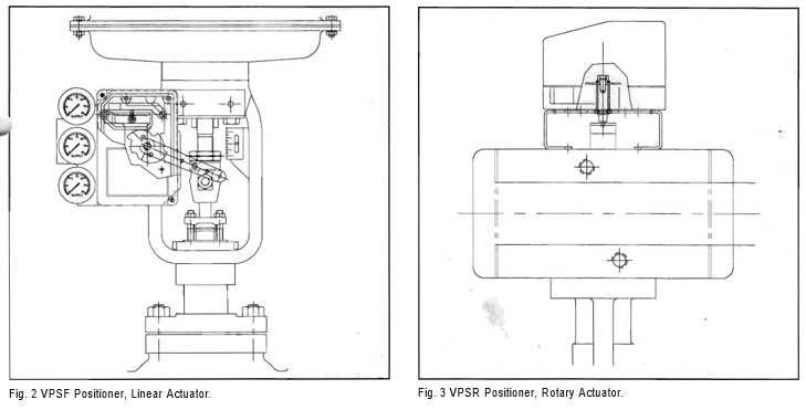
Fig. 2 shows front mounted positioner VPSF on a Diaphragm
actuator.
Fig. 3 represents Positioner, VPSR, mounted on a Rotary ac-
tuator.
With Direct Positioner, an increase in the signal pressure
inreases the output pressure supplied to the actuator through
output port ‘A’ with Reverse Positioner, an increase in the
sig- nal pressure decreases the output pressure supplied
through output port ‘A’.
Calibration
If the calibration have been disturbed in the transit, or
during the installation, calibrate the positioner as under
Zero setting can be conveniently adjusted with the
thumb wheel provided on the zero adjustment lever
and for travel span, adjust the slider on the range
adjustment lever to achie' accurate valve travel. For
calibrations, proceed as follows:-
1. Set signal pressure at 0.2 Kg/cm2 (3psig), loosen the
zero- adjustment-locking knob and adjust the zero until
the valve begins to stroke. Readjust zero to the starting
point of the stroke.
2. Loosen range adjustment locking screw by about 1/8 turn
3. Set signal pressure at 1.0 Kg/cm2(15 psig) and with a
screwdriver, turn the range adjustment gear so that the
valve positions to full stroke.
4. Return to 0.2Kg/cm2g (3 psig) and check the zero.
Repeat steps 1-4 if necessary.
5. Lock the range and zero adjustment settings.

INSTALLATION
When Positioner is specifed for a control valve, the control valve is furnished together with the positioner already mounted, fully calibrated and tested. The following serves as guide lines for the installation:-
-Fhe positioner is clamped on the yoke such that when the valve is at mid stroke, the follower arm on the positioner is approximately horizontal. -Fhis can be achieved by strok- ing the actuator manually to the mid-stroke and position- ing the positioner clamp accordingly.
Considering Direct Positioner, for air to open action, the cam should be installed with the letters L-R facing towards the camshaft and the return spring fed to hole “x” For air to close action, the cam should be installed with the letter L-D facing towards the camshaft and the return spring should be fed into hole “y”.
For piston actuator, air to open, connect port ‘A’ to the bot- tom of the cylinder and port ’B’ to the top of the cylinder and for air to close, connect port ‘A’ to the top of the cylin- der and port ’B’ to the bottom of the cylinder.
For the diaphragm actuator air to close or air to open, the output port “A” of the pilot valve is connected to the actua- tor and output port “B” is plugged.
In case you need to Reverse the Positioner, cam needs to be disengaged , removed and reversed and if the actuator is double acting, then piping also needs to be rerouted.
When positioner is connected to a piston actuator, air sup- ply is generally 4 to 7 Kg/cm2 and when connected to a diaphragm actuator, the air suppy pressure to the positioner should be 0.3 to 0.6 Kg/cm2 higher than the maximum pressure necessary for full valve travel. Be certain to lubri- cate follower pin and take-off arm where contact is made to prevent premature wear.0
MAINTENANCE
No attendance on daily basis is normally required. Only, in case the overall performance level of the controlled loop is not satisfactory and the problem is not suspected to be related to the process, the positioner needs to be checked whether it is responding properly with the variations in the input signal to the positioner. If convenient, the controller on the given loop may be taken on manual control and control valve response checked by introducing mild steady state variations in the controller output that is input signal to the positioner. Valve must position itself in response to the signal fed-in.
In practice majority of control valve failures are caused by the positioner failure. Check that proper supply of air pres- sure is available. By applying mild force on the feed back spring check whether output to the actuator is responding correctly. Check for any mechanical failure of the compo- nents. All positioner components must be secured firmly.
If control valve hunting is observed even when steady state signal is fed in, lhen cause of hunting must be rectified. Check for any loose mechanical joints. Check for air leaks in the actuator casing or tubing connections or on double diaphragm sensor, or relay flange joints. Check stability of the actuator spring for the given process conditions. Check- ing with water soap solution will be adequate to detect air leaks.
If the positioner is faulty and needs removal then process operation should be controlled manually so that the positioner can be checked independenty.
If spare positioner is available it may be desirable to re- place the positioner so that process is not disturbed for prolonged period.